


 12 / 182

ROC800-Series Instruction Manual
1-6
General Information
Revised Jul-14
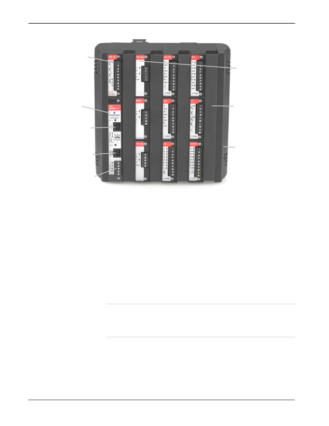
A
Power Supply Module
B
CPU
C
LOI (Local Port) EIA-232 (RS-232D)
D
Built-in Ethernet (Comm1)
E
Built-in EIA-232 (RS-232C) (Comm2)
F
Module (1 of 9 max)
G
Wire Channel Cover
H
Right End Cap
Figure 1-1. ROC809
Module Placement
The left-most slots in the ROC809 (
Figure 1-1
) accommodate the
Power Input module and the CPU module. The remaining nine slots
can accommodate either communication modules or I/O modules (see
Table 1-1
).
Note
:
If you use the optional communications modules, you can
only
place those modules in the three slots (
1
,
2
, or
3
) immediately to
the right of the Power Input and CPU modules. Place I/O
modules in
any
available slot.
Figure 1-2
shows a ROC827 base unit (left) and a typical expansion
backplane (EXP) (right) populated with a full complement of six I/O
modules. Each EXP is composed of the same plastic housing as the
ROC827, contains six I/O slots, and has a powered backplane that easily
attaches to the ROC827 and other EXPs.
B
C
G
H
A
D
E
F